The link here shows an FM receiver with a high level of claimed performance. The diagram here shows a snippet from the paper.
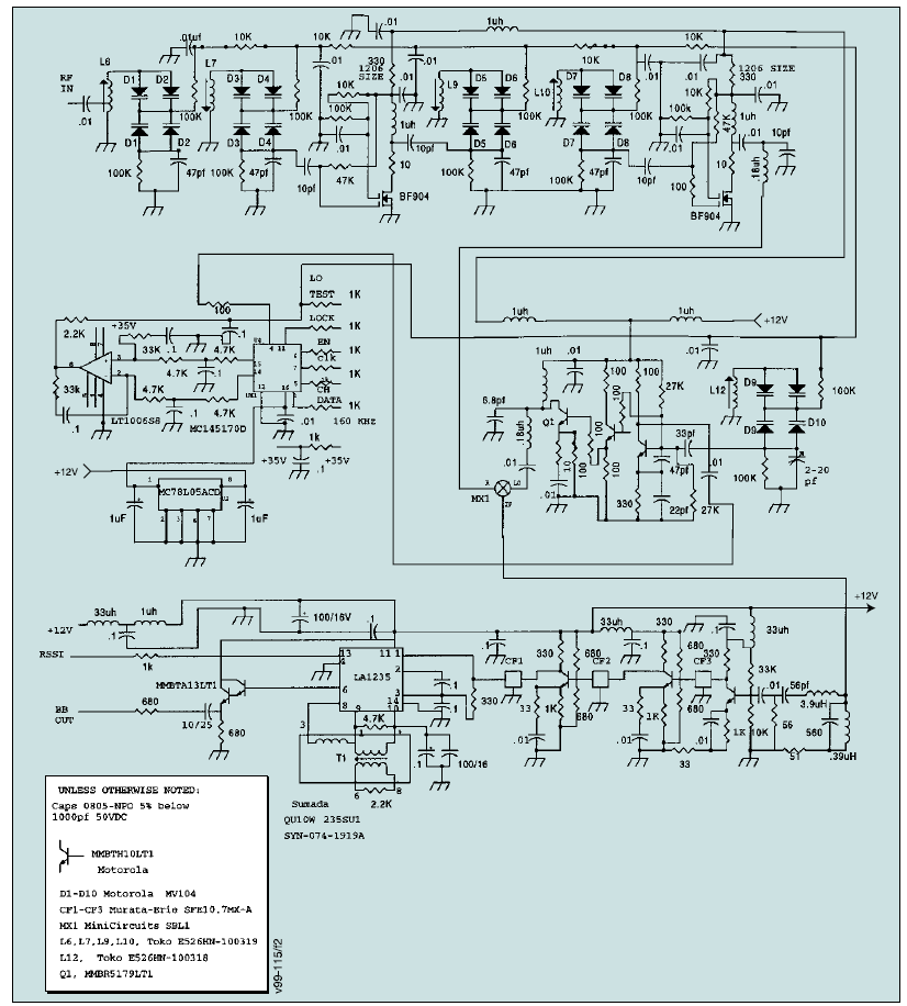
The problem is, most parts are obsolete. It is an opportunity to try to improve areas of the design, such as to use a better PLL possibly. However the core ICs are still available via eBay from a few sellers.
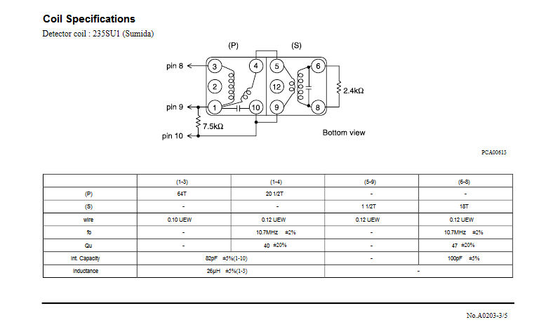
Quadrature Detector Coil
The most difficult part to obtain by far is the quadrature detector coil. A dual coil design is employed which just doesn’t seem to be available anywhere. However the diagram here goes a long way to explain how replica coils may be made. Looking at the second coil (marked S on the diagram), the resonant frequency of coil and capacitor across terminals 6-8 is 10.7MHz of course. Since the capacitance is marked as 100pF, this means that the inductance between pins 6-8 must be 2.21uH.
The LA1235 datasheet suggests the external resistor should be 3.3k, but Ryder’s paper uses a value of 2.2k. With the replica coils, some experimentation may be required with this resistance (and the 4.7k resistance in the circuit too) to set the loaded Q to the optimum value.
The inductance between pins 1-4 and pins 5-9, in parallel with the capacitance between pins 1-10 forms another 10.7MHz LC circuit. The coupling is hard to guess unfortunately. However most small coils don’t have much space, so the chances are that the coil 5-9 was probably just wound on top of coil 6-8.
The coil between pins 1-3 is marked as 64 turns, and is marked as 26uH on the diagram.
It was decided to find two coil kits that, when wound for 26uH and 2.21uH would be approximately 64 and 18 turns respectively.
The second coil (marked S on the diagram) can therefore be replicated with an adjustable inductor kit of approximately 7nH Al value. The Neosid “10 F 1” kit seems ideal.
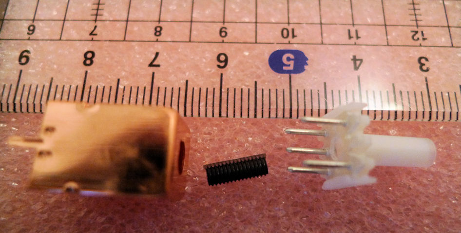
The first coil (marked P on the diagram) can be replicated with an an adjustable inductor kit of about 6nH Al value. Again, the “10 F 1” would be ideal for this, with the tuning slug pulled out a bit more. The Neosid kit is shown here.
The diagram shows that the wire is 0.12mm for all coils except the 64 turn one, which is 0.1mm. These values correspond to 36AWG and 38AWG respectively (or 40 and 42 SWG respectively).
The tuning slug is 7mm in length, so for a coil to create 26uH and fit within 7mm of length, then 0.1mm wire is needed (0.12mm will be too thick).
I had the opportunity to disassemble an LA1235 quadrature coil, just for the interest on duplicating it, and I have seen that the 26uH coil is wound on the same coil form but on the lower part, and there is a gap of 2,5mm between this and the upper 10.7MHz coil. The coil form is a slotted plastic one (maybe you have seen these).
At the moment I have no idea if the 26uH coil has any effect on the distortion level or if it is being affected by the ferrite tuning slug. Other demodulator IC’s use an external inductor of 22uH: CA3089, TDA1220, LA1140… and the all work fine.
BTW good blog, added to my favourites. Bye!
Hi Pep,
Thanks for the comments and useful information!
I’ve finally found someone selling the coils on eBay (for a very
expensive price though) so when I receive them, I’ll try to
disassemble the second can, to see where the 1.5 turn coil is
placed.
Aligning the duplicated coils and testing for linearity will be an
‘interesting’ challenge to say the least! I have limited test
gear so I will need to get a signal generator source (maybe use a
low-cost DDS module maybe).