For constructing transmission lines, coax is useful because it is available in 50 and 75 ohms. For transmission line transformers, the coax can be used, but it is quite thick. Twisted pair or parallel pair wires can be useful in this case. There are general recommendations on the internet on how much to twist (e.g. 1 twist per inch) but no calculations on how this is derived. A wideband transformer definitely needs to be constructed from transmission line, so for example the wire must definitely be paralleled or twisted or coax should be used.
From reading the subject, these are the recommendations: the twist angle should be about 20-45 degrees; I will use 30 degrees. What about the wire? Enamelled copper wire (i.e. Magnet wire in the US) is good, but it seems hard to find the dielectric constant from manufacturer’s web pages. I had more luck finding the info for kynar wire.
30AWG Kynar insulated wire (e.g. Farnell part code 1202481)
Kynar 460 dielectric constant can be found here: http://www.valueplastics.com/technical/material/PVDF/Atofina%20Kynar%20Material%20Data.pdf
Since the constant changes (!) here is a graph of that data from 100Hz to 100MHz:
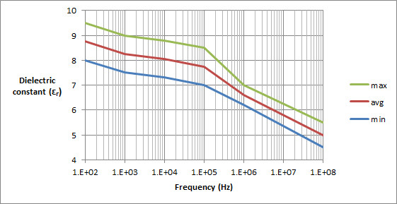
The characteristic impedance calculations use the square root of the constant, so for now I’ll just stick with a value of 6 for the constant, which should be ok-ish for 1MHz to 100MHz.
From “Twisted wire transmission line” by Peter Lefferson, it seems that it is possible to calculated the characteristic impedance of a twisted wire pair by performing the following steps:
1. Calculate the parallel wire characteristic impedance first, ignoring the kynar dielectric constant and just using the air dielectric constant (value 1)
2. Calculate a value called beta, which is based on the twist angle, and the ‘insulation type’ (type meaning hard insulation or soft insulation)
3. Use the result from step 1 and step 2 and the insulator’s (kynar in this case) dielectric constant to calculate the twisted wire characteristic impedance
4. If wrapping around ferrite, add 2 ohms.
Step 1: Parallel wire characteristic impedance ignoring the kynar dielectric constant and just using the air dielectric constant (value 1).
30AWG is 0.01 inch (conductor)
From the data sheet, the diameter including insulation is 0.0195 inch
Characteristic impedance of parallel wires with air constant is:
120 * cosh-1 (0.0195/0.01)
(Note the cosh-1 should have the ‘-1’ in superscript, and cosh-1 is basically Inverse-cosh with a calculator).
This is 154.5 ohms.
Step 2: Calculate beta.
The value beta has a couple of formulas. The reasoning is, that the shape of the insulation can change if the wire insulation is softer.
For hard insulations like enamelled wire,
beta=0.25 + (0.0004 * pitch^2) where pitch is in degrees
Beta is 0.61 for 30 degree, i.e. 0.25 + 0.0004*30*30
For softer insulations like PTFE, it is:
beta=0.25 + (0.001 * pitch^2)
Beta is 1.15 for 30 degrees.
In this case, we use the value 1.15 for 30 degrees twist.
Step 3: Apply the above results and use the dielectric constant from the graph.
Characteristic impedance of the twisted wire is
154.5 / sqrt(ereq)
where ereq = 1 + beta(k-1)
Plugging in beta as 1.15 and k as 6 gives
ereq=6.75
So, the characteristic impedance of the wire twisted at 30 degrees is
154.5 / sqrt(6.75) which is 59.5 ohms.
Step 4:
Add about 1-2 ohms (1.5 ohms average) since this will be wrapped around a ferrite eventually. This means about 61 ohms.
How to twist to 30 degrees?
Use this formula:
twists per inch = tan(pitch)/(pi*D)
where pitch is the angle in degrees, and D is the overall diameter
of the wire in inches (0.0195 in this example).
This means 9.4 twists per inch.
How to decrease the impedance towards (say) 50 ohms?
Increase the twists per inch! It may decrease it by around 10 ohms,
i.e. 50 ohms.
Lets try 35 degrees:
This gives 53.3 ohms + a couple of ohms for the ferrite.
Better to do this using a computer program or excel.