With a BeagleBone Black with the latest image (6th June), I tried this device tree fragment:
(Zip file contains the .dts and the .dtbo)
/*

* pru dts file cape-bone-mytest-00A0.dts

*/

/dts-v1/;

/plugin/;
/ {

compatible = "ti,beaglebone", "ti,beaglebone-black";
/* identification */

part-number = "BB-BONE-MYTEST";

version = "00A0";
fragment@0 {

target = <&am33xx_pinmux>;

__overlay__ {

mygpio: pinmux_mygpio{

pinctrl-single,pins = <

0x8c 0x2f

>;

};
};
};
fragment@2{

target = <&pruss>;

__overlay__ {

status =
};
};
};
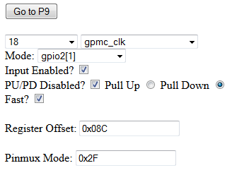
The fragment is responsible for setting <0x8c 0x2f> which is DIL header P8, pin 18 as seen on the pinmux website, set to Input, with no pullup/pulldown:
After copying it to /var/firmware, and then issuing:
SLOTS=/sys/devices/bone_capemgr.9/slots

PINS=/sys/kernel/debug/pinctrl/44e10800.pinmux/pins

export SLOTS

export PINS

echo cape-bone-mytest > $SLOTS
I can see that the fragment is installed, but cat $PINS | grep 88c shows that the pinmux has not changed to 0x2f.
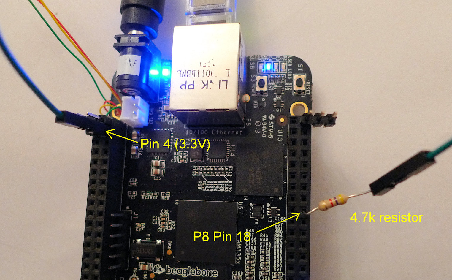
I can see that the pin is floating, because if I connect a 4.7k resistor to pin 18 and the other end to 3.3V or 0V, the multimeter shows the pin is being set high/low correctly.
Then, in my PRU code, I tried to set GPIO2 | GPIO_OE to 1 (which means input), and then read GPIO2 | GPIO_DATAIN but it reads 0 always, regardless of if the 4.7k resistor is going to 3.3V or not.
The PRU code was this (snippets):
// P8_18 GPIO2_1
#define CONF_GPMC_CLK 0x44e1088c
// Set to 0x2f, since the Device Tree fragment failed:
MOV r1, CONF_GPMC_CLK
MOV r0, 0x2f // 2f is GPIO input mode for this pin
ST32 r0, r1
// we need to disable outputs, to use the pins as inputs
// this means writing 1 to the OE register
MOV r3, GPIO2 | GPIO_OE
LBBO r2, r3, 0, 4
SET r2, 1
SBBO r2, r3, 0, 4
INLOOP:
// get GP input
MOV r3, GPIO2 | GPIO_DATAIN; // Address of register to read
LBBO r2, r3, 0, 4 // Store register contents into r2
AND r2.b0, r2.b0, 1<<1 // Mask out everything except the GPIO2_1
// If the register is 0, means the pin went low
QBNE IS_HIGH, r2.b0, 0
IS_LOW:
MOV r2, 1<<21
MOV r3, GPIO1 | GPIO_CLEARDATAOUT // Set the LED0 off
SBBO r2, r3, 0, 4
JMP INLOOP
IS_HIGH:
MOV r2, 1<<21
MOV r3, GPIO1 | GPIO_SETDATAOUT // Set the LED0 on
SBBO r2, r3, 0, 4
JMP INLOOP