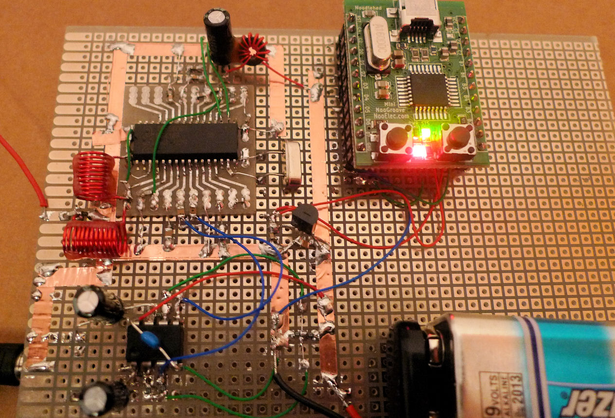
As an experiment, I constructed up this FM receiver. It worked first time – no coil adjustments are necessary. It makes it remarkably easy to get it running. Will post more details soon.
11 thoughts on “TEF6606 receiver”
Leave a Reply Cancel reply
You must be logged in to post a comment.

Hi! im interestig on your ply with tef6606. Now im use same in my project, but i have a problem with meaning datasheet. Could u please post your atmega code? im stop on i2c control. I use arduino, tryed control via datasheet, but nothing success 🙁
Thanks.
Hi, see here:
https://badcafe.co.uk/2012/04/07/implementing-i2c/
At the bottom of that post, there is the example code that tuned the radio to 98.8MHz.
I’m not familiar with arduino, but if it has an I2C library then you can use that, and use the example values mentioned in the post,
i.e. write to address 0xc0, with values 0x00, 0x27, and then write to
address 0xc0 with values 0x21, 0xb8.
All this should tune it to 98.8MHz. The post has the individual bytes briefly explained (the complete explanation is in the datasheet).
To make it adjustable, the values need to be changed (e.g. using up/down buttons, etc).
Thanks, i seen it. Problem is that i have tef6606T v5 and i cant find datasheet for it. Also it have other slave address (0x60, found it via i2c bus sniffer), so old datasheet unusable for me. Also how do u calculate frequencies?
Actually my TEF6606 was v5 too, but the v3 datasheet worked for v5. I couldn’t find a v5 datasheet either. I just used the formula in the v3 datasheet, which needs the 4 registers mentioned to be configured. The registers tuner0 and tuner1 combined set the frequency (page 22 of the v3 datasheet).
The address is the same (I referred to address 0xc0 if you include all 8 bits, but this is the same as 0x60 if you only take the 7 MSB to represent the address). Specifying 0x60 is the correct way actually, but some I2C software refers to it as 0xc0 (as do some NXP datasheets but not others).
Anyway, we both mean the same address. If you I2C library expects 7 bits for the address, then specify 0x60, otherwise specify 0xc0.
I hope it helps! Let me know if you’re still having issues. We have the same revision of IC, so I’m confident it will work.
sorry, but i still cant understand how i can calc freq. how it must be for 107.0 like?
i made dump from mcu i2c bus and have hex array for freq at 87.5 to 108Mhz with 50Khz step. for me it 2026D6-202870. but i still confused with manual calculation 🙁
This makes sense. Lets take the 2026D6 that you saw. Let’s look at it backwards:
The contents of TUNER1 register is D6 and it is the lower 8 bits of 87.5*20. We multiply by 20 according to Table 25 in the datasheet, for 50kHz step. 87.5*20 is 1750, which is 06D6 in hex, and the lower 8 bits is D6.
The contents of TUNER0 register is 26 and it is the upper remaining bits of 87.5*20 in the 5 least significant bits of the register. So, the 5 LSB are 6. The bits 6 and 7 are set to ‘FM Europe, US, Japan’ which is 01 according to Table 22. So, TUNER0 is 00100110 which is 26.
The contents of register MSA is 20. See Table 18 in the datasheet for the explanation: the 4 LSB of this are zero, which mean that subaddress 0 is going to be the register for the next instruction. Subaddress 0 is TUNER0. The MSB are 001 which means ‘preset’ which means ‘tune to new station’ according to table 20 in the datasheet.
So, basically they are doing the same thing, but in 3 register settings. I tuned with 4 register settings in my code as you saw in the post; more inefficient, but it still works.
ohoho! u r excellent teacher, man! now i understand all magic, thank u! now i can calculate freq direcly from my code and drop down preset array!
Excellent, glad to help!
http://www.youtube.com/watch?v=PFKUurFEq4g demo video how it work. Below sample code for arduino-control:
#include
unsigned char frequencyH = 0;
unsigned char frequencyL = 0;
unsigned int frequencyB;
double frequency = 0;
void setup()
{
Wire.begin();
frequency = 1070; //starting frequency
setFrequency();
Serial.begin(9600);
}
void loop()
{
while (Serial.available() == 0);
int reading = Serial.read() – ‘0’;
setFrequency();
Serial.println(frequency);
}
void setFrequency()
{
frequencyB = frequency * 2 + 0x2000;
Serial.println(frequencyB, HEX);
frequencyH = frequencyB >> 8;
Serial.println(frequencyH, HEX);
frequencyL = frequencyB & 0XFF;
Serial.println(frequencyL, HEX);
delay(100);
Wire.beginTransmission(0x60);
Wire.write(0x20);
Wire.write(frequencyH);
Wire.write(frequencyL);
Wire.endTransmission();
delay(100);
}
Very cool : )